Drake AC-4 Power Supply Rebuild
The Drake AC-4 power supply was used to power a number of transmitters and transceivers
in the drake "4" line. I had not seen any pictures of the AC-4 I obtained prior to
purchasing it. I figured, it is just a power supply, how much can go wrong. When I
received the AC-4, and went over it, I did find a number of questionable things.
This page describes my experiences rebuilding the AC-4 to be placed into service.
It is worth noting, I used replacement capacitors from the
Hayseed Hamfest Company as I was looking for
a more original rebuild. While the AC-4 capacitor kit is not yet on the Hayseeed web site,
you can send them an email for all the details.
An alternative to the Hayseed kit is
The Heathkit Shop
AC-4 Power Supply upgrade. There is a good page describing the Heathkit Shop upgrade
installation
here.
As an aside, I am planning to use the AC-4 with my TR-3, as the AC-4 power supply
has a connector for the ALC, which I intend to hook up when I get my L-4B all ready to
go. I got the AC-4 so I could just hook everything up without having to "work on" the
connector on the AC-3. Well, that was the plan...
The starting point
An I mentioned, I did find some things which, for me, needed attention. The first was
the already replaced capacitors. The second was a loose wire from the power transformer
secondary.
While the capacitor replacements would have worked, I thought they just looked ugly.
So I figured I'd replace them. Looking at the various options, the Heathkit Shop upgrade
probably being the most well known, I also checked various suppliers of multi-section
capacitors.
It was during this search I sent Hayseed an email to see if they had an AC-3 or AC-4
set. (They have replacement capacitors for a number of Drake units.) The response said
they did have some available, but the information had not yet been put up on their web
site.
After thinking it over a bit, I decided to order two power supply kits and a TR-3 kit;
since, in addition to the AC-4, I have a TR-3, RV-3, and AC-3. The picures below show
the rebuild as it progressed.
|
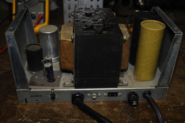
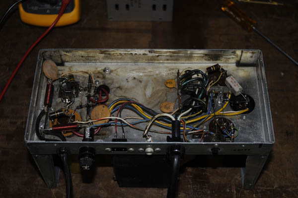
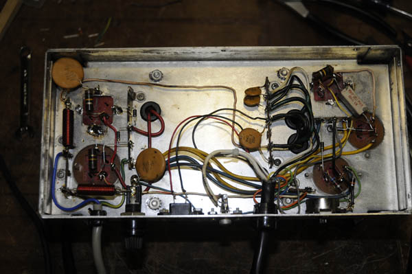
Here are a couple of pictures of the AC-4 as it arrived; needing some TLC.
Prior to starting disassembly, I took several pictures of the original
wiring and layout for reference. This is something I strongly recommend
to anyone attempting to rebuild just about anything: take lots of pictures.
Not pictured is the metal cover to the AC-4.
|
|
|
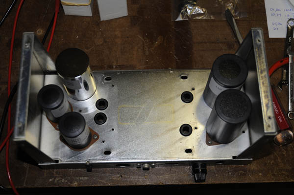
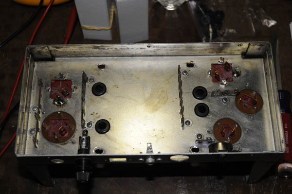
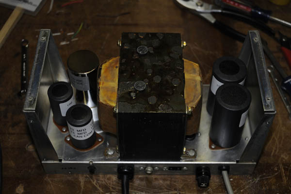
After disassembling the power supply, I was left with a bare chassis. Here
are some pictures of the chassis after I have installed the capacitors,
gromets, terminal strips, and some other miscellaneous bits. I decided to
replace the gromets protecting the power transformer leads, as the original
ones had gotten brittle, and had started to get some significant cracks in
them.
I cleaned the chassis with simple liquid detergent and warm water. I
did not make it perfectly clean, as I wanted some of the "character" to
remain. I used paper towels and compressed air to make sure the chassis
was dry.
|
|
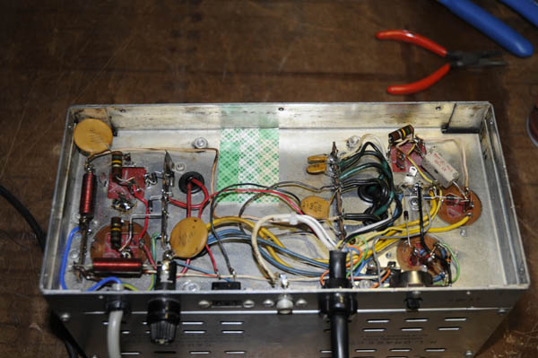
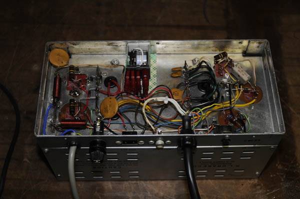
Here is a picture after installing all the components and finishing up the
wiring. While I did reuse many of the original components and wiring, I
did opt to:
- Replace the original two-wire power cord with a three-wire grounded
cord in the interest of safety.
- Replace all the diodes with 1N4004 diodes. No major reason other
then I had them around.
- Replaced the 10k 1/2w resistor as the leads of the original were
too short with the replacement capacitor.
One thing I did discover when wiring everything back up was the color
coded wire in the multi-contuctor cable (to the TR-4) did not match what
was listed in the TR-4 manual. Not a real big issue, but it did mean I had
to check and verify all the wires to the connector to identify the color of
the wires being used.
|
|
|
Here is picure of the rebuilt AC-4 from the top. You can compare this with
the first picture to see the differences.
|
|
Phase 2 Work
Before placing the newly rebuilt AC-4 back into service, I wanted to make one more
change. I wanted to add a relay in the power transformer primart circuit to reduce the
amount of current being handled by the On/Off switch on the TR-3/4. As a point of
reference, prior to the relay upgrade, the load on the On/Off switch contacts was a
minimum of 325 mA (power supply unloaded) and after the load was just over 10 mA. This
is a sgnificant reduction in the load on the contacts.
The materials I used to add the relay were:
- Omron LY1-AC110/120 Power Relay (DigiKey Z781-ND)
- 3M Foam Mounting Tape, catalog number 4013 (Staples, office supply)
- 8 - 0.25 inch (insulated) quick disconnect connectors
- About 1 foot of hookup wire; I used 18 gauge, and used two colors to make
future circuit tracing easier
I had originally planned, and ordered, a socket for the relay. Unfortunately, the
dimensions of socket are not given, and when I received it, I discovered it was much
too wide to fit in the AC-4 chassis. Fortunately, connections to the relay can be made
using standard 0.25 inch quick disconnect (crimp) connectors; available just about
everywhere.
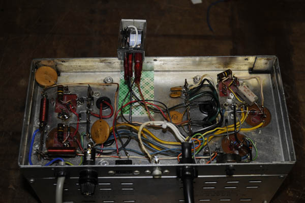
The picures below show how I added the relay.
|
The first step consists of rerouting the wire going from L1/C11 to the
power transformer. In the picture, this is the wire skirting the foam
mounting tape.
The second step was to make a mounting pad/cushion for the relay. This
was originally planned as just a cushion, but that changed; which will be
described below.
|
|
|
Here is the relay ready for mounting. I used black wire for the relay
coil connections, and brown wire for the contact connections. In addition
to the cushion on the chassis, you can also see some of the mounting tape
on the top of the relay.
|
|
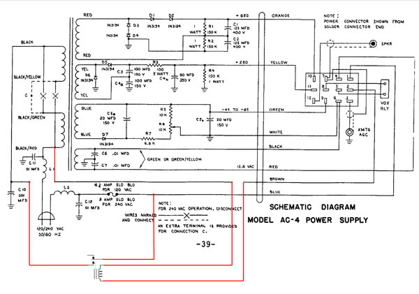
Here is the updated schematic, showing the circuit changes used to add the
relay. Here is a list of the changes:
- Disconnect the brown wire from the terminal strip having the
connections to the power transformer, and add a quick disconnect
connector. This will go to one side of the relay coil.
- Make a small (4 inch) wire with a quick disconnect connector on
one end, and strip and tin the other end. Solder the tinned end
to the power transformer terminal strip, where the (Drake) wire
from L1/C11 is connected. This will go to the other side of the
relay coil.
- Make a small (4 inch) wire with a quick disconnect connector.
Solder the tinned end to the fuse connector, at the same point
as the (Drake) blue wire. This is connected to the common relay
contact.
- Make a small (4 inch) wire qith a quick disconnect connector.
Solder the tinned end to the power transformer terminal strip,
where the (Drake) brown wire was removed at C10. This will
connect to the normally-open relay contact.
It is worth noting my AC-4 wiring differed a bit from the schematic.
Instead of C12 being connected to L2 at the same place on the fuse holder,
it was connected to the other side of the fuse, along with the blue wire.
|
|
|
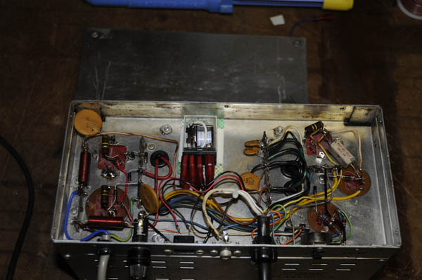
Here is the relay, all connections made, in place with some foam mounting
tape. I also put unused quick disconnect connectors over the unused
lugs on the relay. No sense having possible failure points expose.
Some of you may notice a problem with this installation. More below.
|
|
|
Here is the relay, the same as the previous picture. Except... it has been
moved away ffrom the chassis to allow the base plate (lip) to fit between
the relay and the chassis. This was the problem mentioned in the previous
picture.
This also necessitated a slight change in the relay mounting. Instead
of just using some foam mounting tape to hold the relay to the side of the
chassis, I had to remove that tape and remove some of the backing on the
cushion, making it the new mounting pad for the relay.
|
|
|
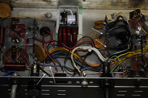
Here is a close-up of the relay and wiring. I've added some arrows to show
most of the connections. The original (Drake) brown wire connection to the
relay coil is hidden under all the other wires.
You can see the new brown wire I added, and the two black wires I added.
I also identified the original (Drake) blue wire.
|
|
|
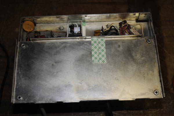
Here is everything set to be closed up. In addition to the mounting pad on
the chassis for the relay, I also added some mounting tape on the cover to
misimize movement of the relay. The tape appears to be offset because the
cover will be flipped over to be attached to the chassis.
|
|
I hope you have enjoyed hearing about this project. It was a fairly straight forward,
and easy, project. I'm sure it will last through many more years of service.
73
Mark, N1VQW
January 8, 2012
